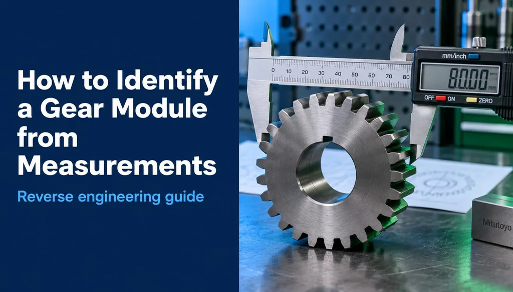
A worn gear arrives with no drawing. Before you can model or reorder it, you need its module (or diametral pitch), pressure angle and, for helical gears, the helix angle. The good news: for most standard gears, a caliper and a tooth count get you there in about five minutes.
§ What you need
- Digital caliper (0.01 mm resolution)
- A marker to tag the first tooth while counting
- Optional: disc micrometer for span-over-teeth (W), or two gauge pins for measurement-over-pins (M)
- The free CADfinity Gear Calculator to check your result against standard modules
§ Step 1 — Count the teeth (z)
Mark one tooth and count all the way round. Count twice. A miscount by one tooth is the most common reason the module comes out as an odd number like 2.05.
§ Step 2 — Measure the tip diameter (da)
With an even number of teeth, measure across two opposite tooth tips. With an odd number, you can't — measure from a tooth tip to the bore and double it relative to the bore centre, or use the root-to-tip method: da = d_bore + 2 × (tip-to-bore distance). Take three readings at different positions and use the largest that isn't on a damaged tooth.
§ Step 3 — Calculate the module
For a standard spur gear (no profile shift): m = da ÷ (z + 2). For inch gears, diametral pitch is DP = (z + 2) ÷ da, with da in inches.
| Measured tip Ø | Teeth (z) | Calculation | Result | Nearest standard |
|---|---|---|---|---|
| 80.0 mm | 38 | 80 ÷ 40 | 2.000 | m 2 |
| 51.9 mm | 24 | 51.9 ÷ 26 | 1.996 | m 2 |
| 63.4 mm | 40 | 63.4 ÷ 42 | 1.510 | m 1.5 |
| 2.083 in | 23 | 25 ÷ 2.083 | 12.0 DP | 12 DP |
§ Step 4 — Module or DP? Check both
Calculate both. If one lands cleanly on a standard (2.000 m) and the other doesn't (12.7 DP), you have your answer. Machines from the US or UK before the 1980s are often DP; most European and Asian equipment is metric.
§ Step 5 — Find the pressure angle
Most modern gears are 20°. Older inch gears are often 14.5°. To confirm, measure the span over k teeth (W) with a disc micrometer and compare it to the theoretical value for 20° and 14.5° — the Gear Calculator's reverse mode does this for you. A mismatch of more than ~0.05 mm on both points to profile shift or a non-standard tool.
§ Step 6 — Helical gears: get the helix angle
- Measure tip diameter and count teeth as above.
- Roll the gear on paper with ink on the tips, or scan it, and measure the tooth angle against the axis.
- The module you get from da is the transverse module mt. The normal module (the one the cutter uses) is mn = mt × cos β.
- Snap mn to a standard value, then recalculate β so the numbers agree.
§ Step 7 — Verify before you model
- Mating gear: check that both gears give the same module.
- Centre distance: a = m × (z1 + z2) ÷ 2 for a standard spur pair. It should match the housing.
- Root diameter: df ≈ m × (z − 2.5). If it's far off, re-check pressure angle and shift.
§ When a caliper isn't enough
Badly worn, broken or non-involute teeth need a 3D scan. Our workflow scans the gear, fits the involute in Geomagic Design X, and recovers module, pressure angle, shift and helix from the clean flanks — not the worn tips. You can also drop the scan into our free AI Reverse Engineering Tool for an instant modeling plan.
Was this helpful?
Take it further
Have a part like this? Or want to learn the workflow yourself?