An STL is not a model. It is evidence of a model. Treating those two things as the same is the root cause of most failed reverse engineering projects — and the reason so many shops can produce a STEP file that opens in CAD but can't be machined, edited, or trusted. This is the six-stage pipeline we run on every production job, and the three quality gates we never skip even when the schedule is screaming.
§ Stage 1 — Intake and scan QC
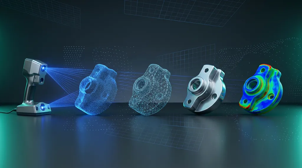
Before anyone opens Design X, the scan itself gets inspected. We check coverage (is every functional surface fully captured?), point density on critical features (sufficient for the smallest fillet?), alignment-marker triangulation, and the deviation between overlapping setups. A scan that fails this gate is rescanned, not modeled. Polishing a bad scan in CAD is the most expensive mistake in reverse engineering.
§ Stage 2 — Mesh repair and decimation
The raw mesh is healed (holes closed, non-manifold edges fixed, intersecting triangles cleaned), then decimated with curvature priority. Functional surfaces stay dense; flat backs and non-functional faces are aggressively reduced. Target: a mesh that is the smallest possible while still passing an Accuracy Analyzer pass within ±0.03 mm of the original.
§ Stage 3 — Reference geometry and datums
Before any solid feature, we define the part's coordinate system. Three planes, the primary axis, any cylindrical reference, plus the datum reference frame the part will be inspected against. These references are locked at the top of the feature tree and never modified downstream. Every sketch, every extrusion, every fillet inherits this foundation — which means any future edit lands on a coherent reference system instead of a stack of accidents.
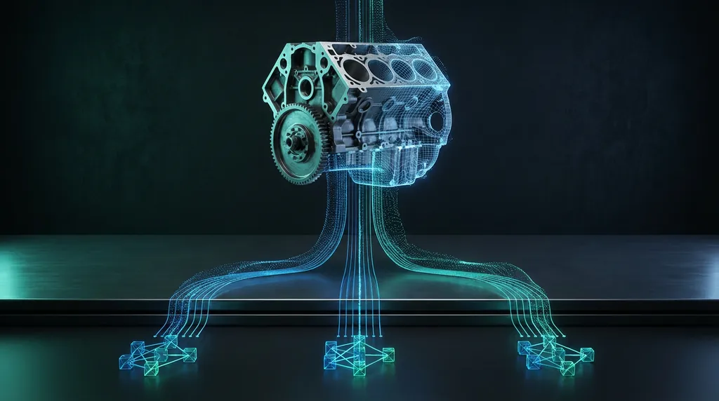
§ Stage 4 — Parametric reconstruction
Now we model. Primitives via Extract Wizard for anything that should be perfectly geometric. Mesh Fit for organic transitions and variable surfaces. Sketches built on extracted profiles, not traced on mesh. Every feature is named, every fillet captured at its design value (not the worn value), every pattern built parametrically. The output is a feature tree that another engineer can open and edit without calling us.
§ Stage 5 — Exchange and verification
Live Transfer to the customer's CAD package (SolidWorks, NX, Creo, Inventor) preserves the feature tree. The transferred model is verified by opening, editing one parametric dimension, and rebuilding — proving the tree survived the exchange. STEP AP242 is generated as the contract deliverable, but the editable native file is what the customer actually uses.
§ Stage 6 — First-article inspection
The model is loaded into Control X or PolyWorks alongside the original scan. A full GD&T-aware inspection report is generated against the customer's drawing (or against a freshly extracted DRF if there is no drawing). Every characteristic is reported with its actual value, its tolerance budget consumed, and a color-mapped deviation visualization keyed to the same datums.
§ Why this discipline matters
Any one stage above can be done well in isolation. The discipline is doing all six in order, on every project, even the small ones. The shops that produce trustworthy reverse-engineered parts are not the ones with the best software — they are the ones that refuse to skip a quality gate to save an afternoon.
If you ship reverse-engineered parts and you don't have a written workflow that looks something like this, build one. Start with the three quality gates and grow the rest of the process around them.
Was this helpful?
Take it further
Have a part like this? Or want to learn the workflow yourself?