Most scan-to-CAD jobs don't fail in the modeling. They fail before the scan, or after it — in the steps people treat as 'admin'. After hundreds of projects, this is the seven-step workflow we run on every production reverse-engineering job, and the reasons each step is non-negotiable.
§ Step 1 — Plan before you scan
Before the scanner comes out of the case, decide three things: what tolerance the final CAD must hit, what the part will be used for downstream (manufacture? simulation? archive?), and which features are critical vs. cosmetic. This drives every choice downstream — scan resolution, alignment strategy, even which CAD package you'll use.
§ Step 2 — Scan strategy & coverage
Pick scanner resolution to match your tolerance, not the part size. A 0.05 mm tolerance feature needs sub-0.02 mm scan resolution — full stop. Plan coverage so every critical feature is hit from at least two angles, and use sprayed reference targets on shiny or symmetric parts so alignment doesn't drift.
§ Step 3 — Mesh cleanup
- Run Health Wizard (or equivalent) to fix non-manifold edges and remove spikes under your noise floor
- Decimate carefully — aim to lose noise without losing curvature detail
- Hole-fill ONLY on non-critical regions; leave critical features visibly broken so you don't model into a fabricated surface
- Save a 'master mesh' before any edits — you will need it for validation in step 7
§ Step 4 — Alignment & datums
Establish the coordinate frame before you draw a single sketch. Use the part's functional datums — the surfaces that mate, the axes that rotate — not whatever orientation the scan happens to land in. A misaligned mesh forces every downstream feature to fight the coordinate system, and the errors compound.
§ Step 5 — Region segmentation
Run automatic region grouping to classify mesh patches by curvature: planes, cylinders, cones, freeform surfaces. This single step is what separates a 2-hour modeling session from a 2-day one. The cleaner your regions, the faster every fitted feature snaps into place.
§ Step 6 — Parametric rebuild vs auto-surface
Two paths from here. Parametric rebuild — sketches, extrudes, revolves, lofts — gives you a fully editable feature tree downstream, ideal when the part will be modified or manufactured. Auto-surface (mesh fit) gives you a near-perfect class-A skin, ideal when the geometry is organic and modification isn't on the table. Pick based on the downstream job from step 1, not based on which is faster today.
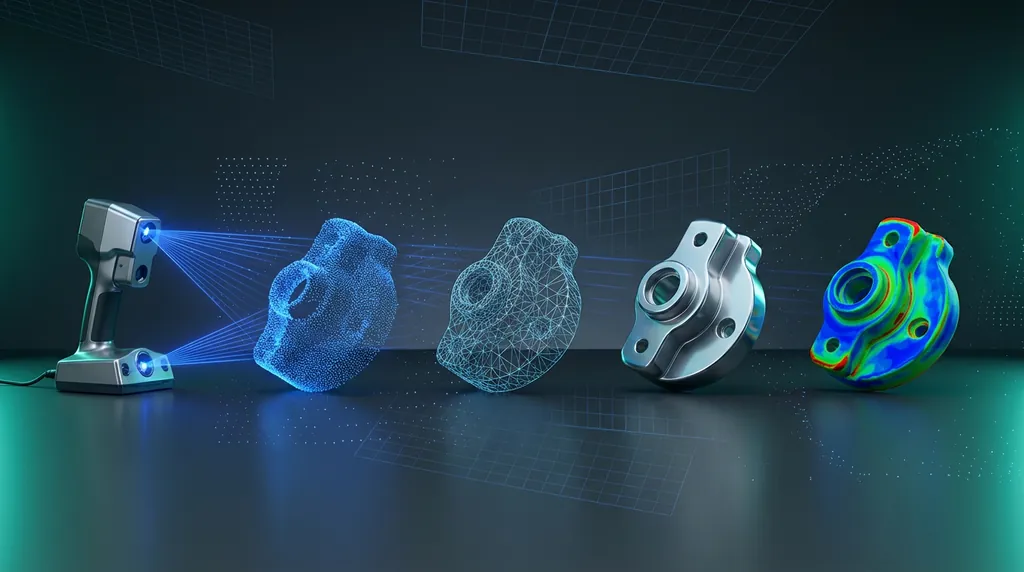
§ Step 7 — Validate against the scan
This is the step everyone wants to skip. Don't. Run a deviation analysis between your finished CAD and the master mesh from step 3. Critical features must hit your spec from step 1. Color-map the result, document deviations on cosmetic surfaces, flag and rework anything that drifts on critical ones. Ship the deviation report alongside the CAD — it's the only proof that the part you delivered matches the part you scanned.
§ The bottom line
Scan-to-CAD is a chain. Skip planning and you scan the wrong things. Skip alignment and every feature fights you. Skip validation and you ship a model nobody can defend. Run the chain end-to-end on every job — even the small ones — and the modeling itself becomes the easy part.
We teach this workflow hands-on in our reverse-engineering training, and we run it daily on client projects. If you want to see it on your part, that's what we're here for.
Was this helpful?
Take it further
Have a part like this? Or want to learn the workflow yourself?